Automobile Info- New cars,bikes model,new automobile technology

Sunday, June 28, 2015

How Electric Power Assisted Steering Works(ePAS)


Electric power Assisted Steering(ePAS) system has following components:-

1. Electric Motor
2. Reduction Gear
3. Torque Sensor
4. Vehicle Speed Sensor
5. ECU
6. Steering Angle Sensor

In the picture clear all the position of components.


Electric Control Unit(ECU) calculate the assisted torque on the bases of wheel position, vehicle speed and torque applied by driver on steering wheel.
then ECU give signal to electric motors which rotates the steering gear which reduce the torque required  by driver.


To know more about 
Electric Power Assisted Steering Works click here
Read more ...

Thursday, June 18, 2015

What is electric Power Assisted Steering(ePAS)

Power Assisted Steering (PAS) is a supplement the torque that deliver by driver to the steering wheel for turning. hydraulic and electric mechanism use for adding additional power to steering.When electric motor used for generating the power in steering wheel, this system called Electric Power Assisted Steering(ePAS)

Electric Power system (EPS) eliminates many hydraulic power system(HPS) components like the pump, hoses, fluid, drive belt. that's why EPS tend to be smaller and lighter than HPS.

EPS system have variable power assist, which provide more assistance at lower car speed and less assistance at higher speeds. it don't require any significant power to operate when no steering is required.

EPS system are four type based on the position of the assisted motor
1. C-EPS(Column Assist Type):- in this system, power assist unit, torque sensor, and controller all connected to the steering column.
2. P-EPS(Pinion Assist Type):- in this type, power assisted unit is connected to the steering gear's pinion shaft. 
3. D-EPS(Direct Drive Type):- this system has low inertia and friction because the steering gear and assisted unit are single unit. 
4. R-EPS(Rack Assist Type):- this unit connected to the steering gear.this unit used in heavy vehicle due to their relatively low inertia from reduction gear ratios.

To Know How ePAS system Works Click Here


Read more ...

Friday, May 15, 2015

HOW DOES TORQUE CONVERTER WORKS


TORQUE CONVERTER

Here we discuss about the what is torque converter and how its work. the basic function of torque converter in the Automatic Transmission System. the torque converter takes the place of a clutch in vehicle for power transmission from engine to transmission system. Torque converter directly connects to engine's flex plate( flywheel).like clutch system in conventional manual transmission torque converter is also provide a means by which to connect and disconnect the engine's power to driven load.


Components Torque Converter

There are four components of torque converter;-

1. Impeller
2. Turbine
3. Stator
4. Transmission Fluid


 Function of Torque Converter

The turbine is connected to the transmission input shaft and impeller connected with engine flywheel. when engine turns the impeller which impart a force on a transmission fluid. this fluid pressure rotates the turbine and sending a torque to the transmission.

The transmission fluid flows in a loop between the impeller to the turbine. then this coupling suffers from severe churning losses as the fluid returning from the turbine has a component of its velocity that opposes the rotation of the impeller. That is, fluid returning from the turbine works against the impeller's rotation and thus against the engine 


The stator sits between the impeller and turbine. Its goal is to minimize churning losses and to increase torque output by redirecting the fluid as it returns from the turbine to the impeller. The stator directs the fluid so that the majority of its velocity is in the direction of the impeller, helping the impeller move, and thus adding to the torque produced by the motor.
The stator sits on a one-way clutch. It can rotate in one direction only when the turbine and impeller are moving at approximately the same speed (like during highway driving). The stator either rotates with the impeller or not at all. Stators don't always multiply torque, though. It provide more torque when  either at standing condition or while accelerating, but not during highway cruising.
In addition to the one-way clutch in the stator, some torque converters contain a lock-up clutch whose job it is to lock the turbine with the torque converter housing so that the turbine and impeller are mechanically connected. Eliminating the fluid coupling and replacing it with a mechanical connection ensures that all of the engine's torque is transmitted to the transmission input shaft

Automatic Transmission Fluid (ATF)  Flow Direction


 direction of fluid between impeller to turbine


Torque converter uses in automatic transmission system in vehicle. To know more about Automatic Transmission System Click here

To Know More About Vehicle click below link

What is ABS Braking System

Read more ...

WHAT IS AUTOMATIC TRANSMISSION SYSTEM IN AUTOMOBILE

WHAT IS AUTOMATIC TRANSMISSION SYSTEM


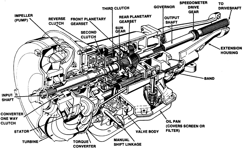
Automatic Transmission can automatically change gear ratios as the vehicles moves, free from having to shift gear manually. like other transmission systems on vehicle, its allow to run at a relatively high rotation speed without human interference. In this type of vehicle, driver not need to change the gear a smart automatic system change the speed ratio according to vehicle running condition.


Hydraulic transmission system consist major three components:  


1. Torque Converter

2. Planetary Gear Train
3. Hydraulic Controls


Torque Converter:

The torque converter takes the place of clutch on a conventional manual transmission. The goal of the torque converter is to provide a means by which to connect and disconnect the engines power to the driven load.


To know more about Torque Converter click here


Planetary Gear Train:

It consisting of planetary gear sets as well as clutches and bands. It is mechanical system that provide different gear ratios.
A planetary gearset consists of a sun gear in the center, planet gears that rotate around the sun gear,a planet carrier that connects the planet gears and ring gear on the outside that meshes with the planet gears. by using clutches or bands, we can prevent certain components from moving and we can alter the input and output of the system and thus change of overall gear ratio.clutches or bands are used to just change which components rotate and which stay stationary. these clutches are actuated by the valve body, their are sequence controlled by the transmission's internal programming.
Principally, a type of device known as a sparg or roller clutch is used for routine upshifts or downshifts. operating much as a ratchet, it transmits torque only in one direction, free-wheeling in the other. the advantage of this type of clutch is that its eliminates the sensitivity of timing a simultaneous clutch release & apply on two planetaries. simply taking up the drivetrain load when actuated , and releasing automatically when the next gear's sparg clutch assumes the torque transfer. These band semi manually controlled for low range or reverse gear.manually gear operate on the planetary drum's circumference. these bands are not working when driver select drive/overdrive range. The torque being transimitting by the sparg clutches instead bands are used for braking.


Hydraulic Control:

An oil pump uses for controlling various clutches and bands modifying the speed of the output depending on the speed of car. A pump is typically gear pump mounted between the torque converter and planetary gearset. 
1. It draws transmission fluid from a sump and pressurize it which is needed for transmission component to operate. 
2.The input for the pump is connected to torque converter housing, which is bolted with engine flywheel so pump provide the pressure whenever the engine is running.
3. pump works only when the engine in running condition. so this is impossible to push start a vehicle equipped with automatic transmission.

A GOVERNOR is connected to the output shaft which regulates the hydraulic pressure depending on the vehicle speed. engine load is monitor either by a throttle cable or a vacuum modulator.

The valve body is the hydraulic control center the receives pressurized oil from main oil pump. This pressure is regulated and used to run a network of spring-loaded valves, check balls and servo pistons The valves use the pump pressure and the pressure from a centrifugal governor (as well as hydraulic signal from the range selector valves and the throttle valve or modulator) to control which ratio is selected on the gearset as the vihicle and engine change speed, the difference between the pressure changes, causing different sets of valves to open and close. these clutch and brake band actuators controlling the operation of the planetary gearset to select the optimum gear ratio for current operating conditions.
Now a days, the valves are controlled by electro-mechanical servos which are controlled by the electronic engine control unit (ECU) or separate transmission control unit (TCU).


To Know More About Vehicle click below link

What is ABS Braking System


Read more ...

Wednesday, June 19, 2013

Difference Between ABS Braking and Non ABS Braking


ABS Braking Vs Non ABS Braking

The beauty is that ABS system allow for steering during emergency braking whereas if you hit the brakes and skid forward you can not steer away from harm's ways. ABS systems don't necessary make you stop in a shorter distance, they make your drive safer by allowing you to steer during the emergency braking scenario whereas with non-ABS equipped vehicles you can not.


For road use, ABS is an absolute must as it will allow you to steer out of the way of unexpected hazards. Diagrams below explain the practical reasons for ABS.

Braking hard on a slippery surface with ABS or Without ABS


In the diagram above, the driver hits the brakes hard on a slippery surface then steers successfully manages to avoid the obstacle with ABS. ABS prevents the wheels from locking and this allows you steer.

Without ABS, as the driver applies the brakes the wheels lock, Despite applying steering lock, the car continues straight ahead due to the loss of steering control and a collision results.


Read more ...

Monday, June 17, 2013

WHAT IS ABS BRAKING SYSTEM AND HOW IT WORKS


Anti-lock Braking System (ABS) 

ABS is an automobile safety system that allows the wheels on a motor vehicle to maintain tractive contact with the road surface according to driver inputs while braking, preventing the wheels from locking up (ceasing rotation) and avoiding uncontrolled skidding. It is an automated system that uses the principles of threshold braking and cadence braking.

How ABS Works

ABS includes a central electronic control unit (ECU), four wheel speed sensors, and at least two hydraulic valves within the brake hydraulics. The ECU constantly monitors the rotational speed of each wheel with the help of wheel speed sensor; if ABS system detects that one wheel is slowing down more rapidly than the others, a condition indicative of impending wheel lock, it automatically reduces the brake pressure on this wheel by opening release valve in hydraulic cylinder , thus reducing the braking force on that wheel; the wheel then turns faster. Conversely, if the ECU detects a wheel turning significantly faster than the others, brake hydraulic pressure to the wheel is increased so the braking force is reapplied, slowing down the wheel. This process is repeated continuously and can be detected by the driver via brake pedal pulsation. Some anti-lock systems can apply or release braking pressure 16 times per second.

ABS breaking system

ABS Braking Components

There are three main components of ABS:

1. Speed Sensors
2. Hydraulic Modulator
3. Controller 


Speed sensors:
The speed sensors, which are located at each wheel, or in some cases in the differential, provide this information of wheel speed.

Hydraulic Modulator:
Hydraulic modulator has two main component :


Valves:
There is a valve in the brake line of each brake controlled by the ABS. On some systems, the valve has three positions:
In position one, the valve is open; pressure from the master cylinder is passed right through to the brake.
In position two, the valve blocks the line, isolating that brake from the master cylinder. This prevents the pressure from rising further should the driver push the brake pedal harder.
In position three, the valve releases some of the pressure from the brake.


Pump:
When the ABS system operates the brake lines lose pressure. The pump re-pressurizes the system.


Controller:
The controller is an ECU (Electronic control unit) type unit in the car which receives information from each individual wheel speed sensor, in turn if a wheel loses traction the signal is sent to the controller, the controller will then limit the brake force (EBD) and activate the ABS modulator which actuates the braking valves on and off.
Read more ...

Sunday, April 28, 2013

WHAT IS AIR BAG IN CAR?


An airbag is a vehicle safety device. Airbags are balloon-like devices that expand when a car experiences a collision, providing a cushion of air that prevents a person bashing their face on the dashboard or steering wheel and suffering concussion.


Generally, air bags are designed to deploy when the severity of a crash reaches a preset impact  value. Depending on the specific vehicle model, this impact is normally equivalent to a vehicle crashing into a solid wall at 13-23 km/h. Air bags most often deploy when a vehicle collides with another vehicle or with a solid object like a tree. 

Airbags are usually fitted in the front seats. A car that is described as having a “driver’s side airbag” has one airbag only, designed to protect the driver. If a car has “dual airbags,” it has one airbag for the driver and another air-bag for the passenger.

air bag in car


How Air Bag Works


Air bags inflate when a sensor detects a front-end crash severe enough to trigger their deployment. The sensor sends an electric signal to start a chemical reaction that inflates the air bag with harmless nitrogen gas. All this happens faster than the blink of an eye. Air bags have vents, so they deflate immediately after absorbing the energy of an occupant. They cannot smother you and they don't restrict your movement. The "smoke" you may have seen in a vehicle after an air bag demonstration is the nontoxic starch or talc that is used to keep the insides of the air bag from sticking together.


Read more ...

ShareThis