Automobile Info- New cars,bikes model,new automobile technology
Showing posts with label AUTOMATIC TRANSMISSION SYSTEM. Show all posts

Friday, May 15, 2015

HOW DOES TORQUE CONVERTER WORKS


TORQUE CONVERTER

Here we discuss about the what is torque converter and how its work. the basic function of torque converter in the Automatic Transmission System. the torque converter takes the place of a clutch in vehicle for power transmission from engine to transmission system. Torque converter directly connects to engine's flex plate( flywheel).like clutch system in conventional manual transmission torque converter is also provide a means by which to connect and disconnect the engine's power to driven load.


Components Torque Converter

There are four components of torque converter;-

1. Impeller
2. Turbine
3. Stator
4. Transmission Fluid


 Function of Torque Converter

The turbine is connected to the transmission input shaft and impeller connected with engine flywheel. when engine turns the impeller which impart a force on a transmission fluid. this fluid pressure rotates the turbine and sending a torque to the transmission.

The transmission fluid flows in a loop between the impeller to the turbine. then this coupling suffers from severe churning losses as the fluid returning from the turbine has a component of its velocity that opposes the rotation of the impeller. That is, fluid returning from the turbine works against the impeller's rotation and thus against the engine 


The stator sits between the impeller and turbine. Its goal is to minimize churning losses and to increase torque output by redirecting the fluid as it returns from the turbine to the impeller. The stator directs the fluid so that the majority of its velocity is in the direction of the impeller, helping the impeller move, and thus adding to the torque produced by the motor.
The stator sits on a one-way clutch. It can rotate in one direction only when the turbine and impeller are moving at approximately the same speed (like during highway driving). The stator either rotates with the impeller or not at all. Stators don't always multiply torque, though. It provide more torque when  either at standing condition or while accelerating, but not during highway cruising.
In addition to the one-way clutch in the stator, some torque converters contain a lock-up clutch whose job it is to lock the turbine with the torque converter housing so that the turbine and impeller are mechanically connected. Eliminating the fluid coupling and replacing it with a mechanical connection ensures that all of the engine's torque is transmitted to the transmission input shaft

Automatic Transmission Fluid (ATF)  Flow Direction


 direction of fluid between impeller to turbine


Torque converter uses in automatic transmission system in vehicle. To know more about Automatic Transmission System Click here

To Know More About Vehicle click below link

What is ABS Braking System

Read more ...

WHAT IS AUTOMATIC TRANSMISSION SYSTEM IN AUTOMOBILE

WHAT IS AUTOMATIC TRANSMISSION SYSTEM


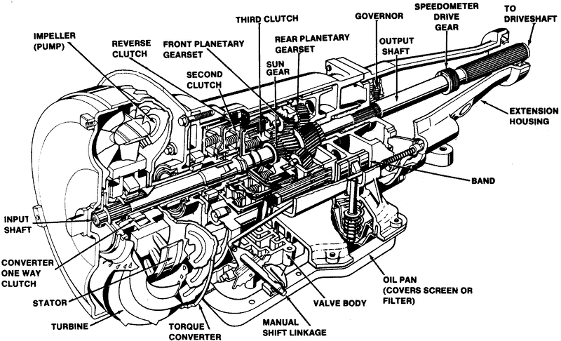
Automatic Transmission can automatically change gear ratios as the vehicles moves, free from having to shift gear manually. like other transmission systems on vehicle, its allow to run at a relatively high rotation speed without human interference. In this type of vehicle, driver not need to change the gear a smart automatic system change the speed ratio according to vehicle running condition.


Hydraulic transmission system consist major three components:  


1. Torque Converter

2. Planetary Gear Train
3. Hydraulic Controls


Torque Converter:

The torque converter takes the place of clutch on a conventional manual transmission. The goal of the torque converter is to provide a means by which to connect and disconnect the engines power to the driven load.


To know more about Torque Converter click here


Planetary Gear Train:

It consisting of planetary gear sets as well as clutches and bands. It is mechanical system that provide different gear ratios.
A planetary gearset consists of a sun gear in the center, planet gears that rotate around the sun gear,a planet carrier that connects the planet gears and ring gear on the outside that meshes with the planet gears. by using clutches or bands, we can prevent certain components from moving and we can alter the input and output of the system and thus change of overall gear ratio.clutches or bands are used to just change which components rotate and which stay stationary. these clutches are actuated by the valve body, their are sequence controlled by the transmission's internal programming.
Principally, a type of device known as a sparg or roller clutch is used for routine upshifts or downshifts. operating much as a ratchet, it transmits torque only in one direction, free-wheeling in the other. the advantage of this type of clutch is that its eliminates the sensitivity of timing a simultaneous clutch release & apply on two planetaries. simply taking up the drivetrain load when actuated , and releasing automatically when the next gear's sparg clutch assumes the torque transfer. These band semi manually controlled for low range or reverse gear.manually gear operate on the planetary drum's circumference. these bands are not working when driver select drive/overdrive range. The torque being transimitting by the sparg clutches instead bands are used for braking.


Hydraulic Control:

An oil pump uses for controlling various clutches and bands modifying the speed of the output depending on the speed of car. A pump is typically gear pump mounted between the torque converter and planetary gearset. 
1. It draws transmission fluid from a sump and pressurize it which is needed for transmission component to operate. 
2.The input for the pump is connected to torque converter housing, which is bolted with engine flywheel so pump provide the pressure whenever the engine is running.
3. pump works only when the engine in running condition. so this is impossible to push start a vehicle equipped with automatic transmission.

A GOVERNOR is connected to the output shaft which regulates the hydraulic pressure depending on the vehicle speed. engine load is monitor either by a throttle cable or a vacuum modulator.

The valve body is the hydraulic control center the receives pressurized oil from main oil pump. This pressure is regulated and used to run a network of spring-loaded valves, check balls and servo pistons The valves use the pump pressure and the pressure from a centrifugal governor (as well as hydraulic signal from the range selector valves and the throttle valve or modulator) to control which ratio is selected on the gearset as the vihicle and engine change speed, the difference between the pressure changes, causing different sets of valves to open and close. these clutch and brake band actuators controlling the operation of the planetary gearset to select the optimum gear ratio for current operating conditions.
Now a days, the valves are controlled by electro-mechanical servos which are controlled by the electronic engine control unit (ECU) or separate transmission control unit (TCU).


To Know More About Vehicle click below link

What is ABS Braking System


Read more ...

ShareThis